When designing electronic components, much time and effort goes into anticipating and managing heat flows. Heat is an inevitable byproduct in electronics, and it’s a growing problem as complexity increases and current draws rise. The solution is to perform a lot more thermal analysis before finalizing a design, and that means a lot more Computational Fluid Dynamics (CFD) work.
CFD produces impressive graphics that show how air flows around physical objects, and it’s tempting to accept these at face value. However, in the real-world, airflow is complex and therefore, hard to simulate. Small errors in assumptions or input data can lead to wildly misleading results, which is why it’s critical to assess the accuracy of the CFD model. But first, let’s examine why CFD is used when designing electronic components.
Heat: The Big Challenge in Electronics
Electricity meets resistance when flowing through any kind of device, and that creates heat. The more densely packed the various components and the higher the current, the more heat is generated. If not dissipated, that heat will damage the circuit board, plastic mountings and the electrical devices. It may break down solder joints and causes expansion that could break connections and cause parts to buckle.
Modern electronic components pack ever more devices into a smaller volume. Meanwhile, current is increasing as the components grow in complexity. To avoid heat-related problems in service, development engineers go to great lengths to manage heat flows. This is why thermal analysis has become such a vital part of electronic product design.
Thermal analysis lets engineers predict how air will flow over and through electronic enclosures. It consists of modeling using CFD, followed by verification and validation to measure model accuracy. Analyzing thermal behavior before a component is produced avoids repeated design-manufacture-test iterations and saves time in product development.
Modeling Heat Flows
Much like Finite Element Analysis (FEA), CFD is a mathematical software tool used to simulate the physical world. However, while FEA deals primarily with the behavior of structures, CFD is about fluid flows. That steps up the underlying math to Navier-Stokes equations and requires a great deal of computer power.
Heat is transferred through conduction, convection and radiation. Conduction can be modeled with FEA as it relies on the physical properties of materials. Convection is more complicated. It can, for instance, be forced or natural and requires convection coefficients that may or may not be known. CFD is used for modeling both conduction and convection. (It can also model heat transfer by radiation, although as the impact is relatively small, this is usually ignored.)
Verification and Validation
CFD provides more detail on heat flow than can be obtained through actual measurement and experimentation. Obviously, this can lead to much-improved design, but only if the modeling results are accurate.
Accuracy is assessed in two ways: through verification and validation. Verification is about assessing the correctness of the math and programming. The American Institute of Aeronautics and Astronautics (AIAA), considered the authority on the subject, describe it as, “the process of determining if a simulation accurately represents the conceptual model.”
Validation comes after verification. Again, referencing the AIAA, this “is the process of determining how accurately a simulation represents the real world.” Comparing the output of the CFD simulation with real-world testing will always reveal a difference between the two.
Complete agreement between simulation and real-world is impossible: the real world is just too complex for every variable to be incorporated precisely. The goal of validation is to show that the model accuracy is sufficient for the intended purpose. It does not explain the source of the difference. While there may be errors or faulty assumptions in the model, it’s also possible that the experimental data used in the comparison is at fault.
Having established the difference between experimental and CFD results, the next step is to determine where changes are needed. Assessing the sources of uncertainty in each identifies opportunities for correction and refinement. Model, experimental design, or both are tweaked and CFD and experimentation repeated. If the comparison shows the difference is within acceptable limits, there’s no need to go any further. If improvement is needed, another iteration will follow.
Gaining Confidence in the Model
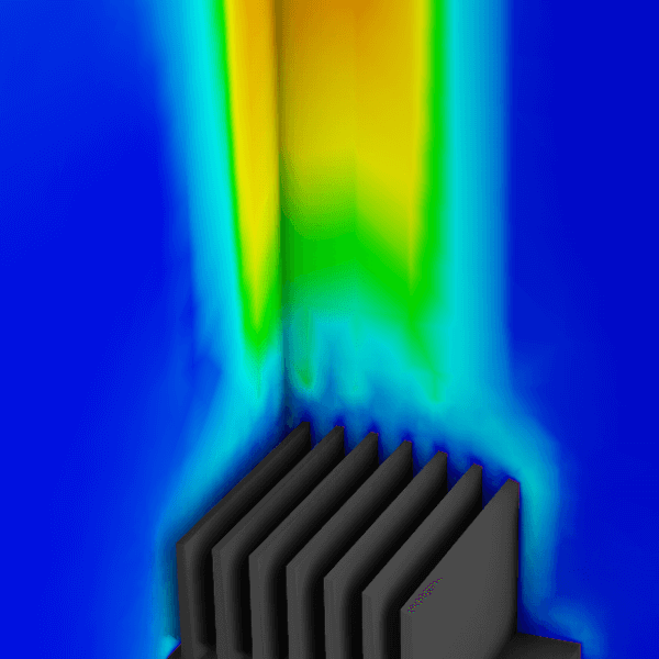
Heat flows over and around electronic components are too complex to be determined purely through experimentation. Plus, this would require building physical prototypes for testing and delay the development process. Instead, CFD is used to model how airflow will take away thermal energy.
Confidence in this thermal analysis is achieved through verification and validation. The validation process entails comparing the output of the simulation with measurements made in the physical world. These will inevitably differ, but that difference is used to refine both the model and measurement process. The sequence of steps is repeated until the error between the two is close enough for the purposes of the study. When that point is reached, the development team can be confident of the electronic component performing as expected.